- File types and
- Importing plans
- Creation
- Checks
- CAD file
- Management of reference files
File types and tips
The following file types can be imported into ICON:
•DXF/DWG: CAD file (BricsCAD, AutoCAD, Civil 3D, etc.)
•IFC: BIM file (BricsCAD, Civil 3D, Revit, etc.)
•TXT/XML : CSV: ASCII file (Excel, Notepad++, etc.)
•PDF : Presentation file (Adobe Acrobat, AutoCAD, etc.)
*The use of PDFs is not recommended, the reasons for this will be explained in this presentation.
DXF/DWG/IFC
DXF is the CAD file type to be prioritized.
DWG is also good, but you need to prepare your file well (cleaning and selection of essential elements) to maximize the potential of the instruments.
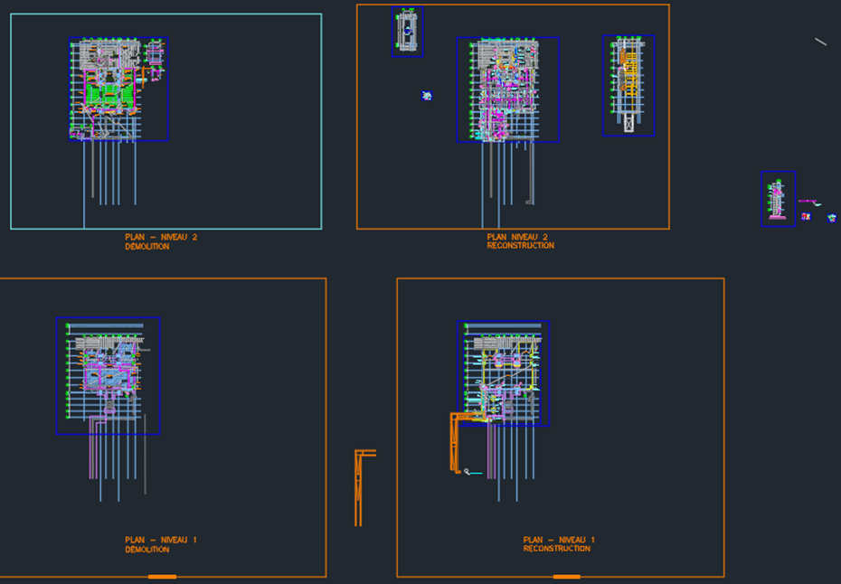
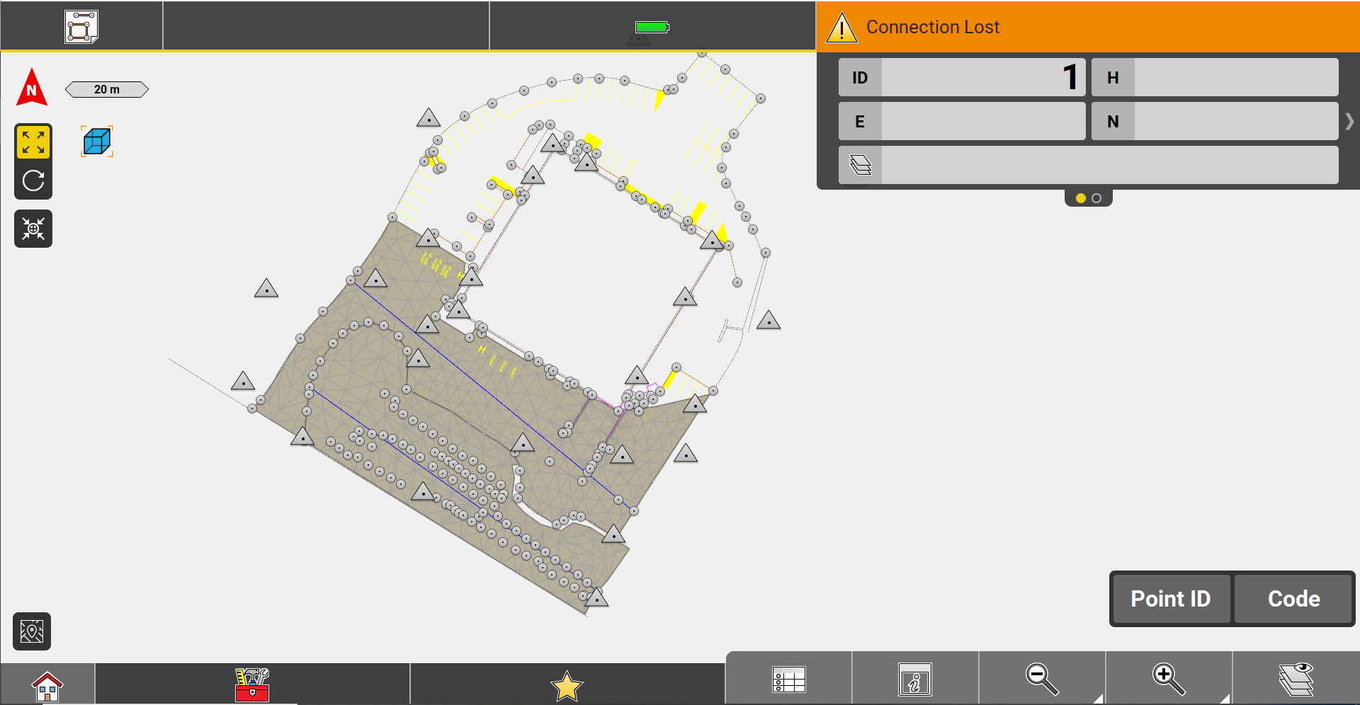
In the following image, a DWG CAD that clearly needs a good cleaning before being imported
It is possible that iCON is unable to import a file. An error message will appear on the screen. There are several reasons for this problem...
•The presence of accents or spaces in the file name
•The size of an IFC file exceeds 150 MB.
•Other file sizes exceed 8 Mb.
•The file is corrupted (this may be due to the use of certain software/versions).
•The file was created with an educational license from Autodesk.
*You can check on a CAD program for errors. Re-save your data file (sometimes a change of format will do the trick, like DXF 2010, for example) and if the import still fails, call technical support!
TXT/XML : CSV
TXT and CSV files are two standard extensions for ASCII files, used for point lists.
If you want to edit an ASCII file in Excel, you have to import it via Data > Import and transform data > From a text/CSV file. To edit a list of points in another way, you can simply open the file in Notepad or Notepad++..
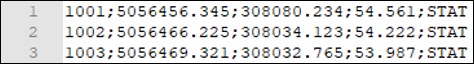
txt file opened in Notepad++.
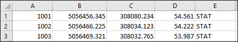
csv file imported into Excel
Make sure :
- To know the order of the data (ID, North, East, Height, Code, Attributes...)
- To know which is the field separator (comma, semi-colon, tab, space)
- That each line follows the same structure (no line breaks or incomplete lines)
- To name your file with the extension .TXT
Importing plans
Plans can be imported when a project or job is created or at any time from the Import menu:
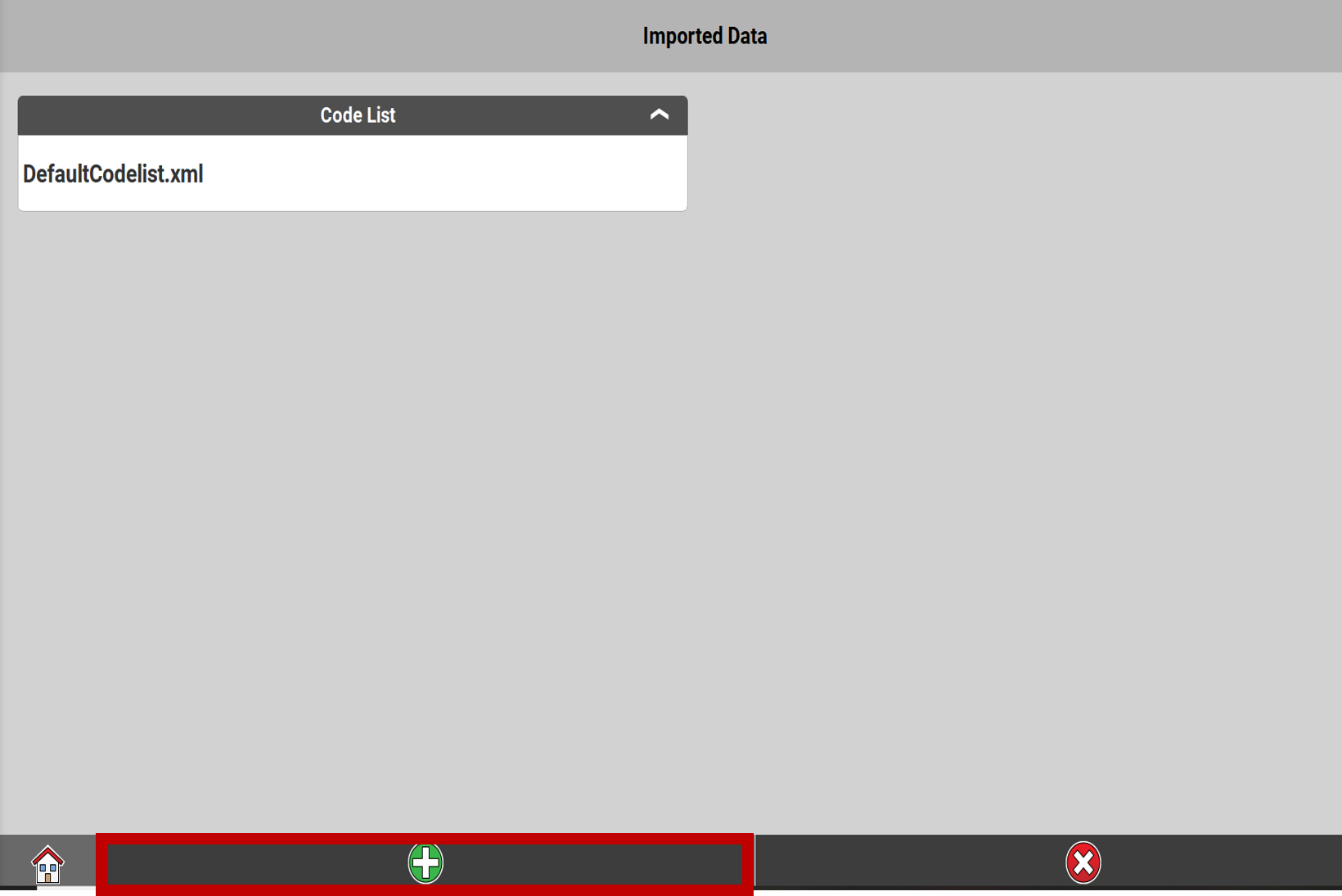
1.From the main menu, press Import.
2.Press the green plus 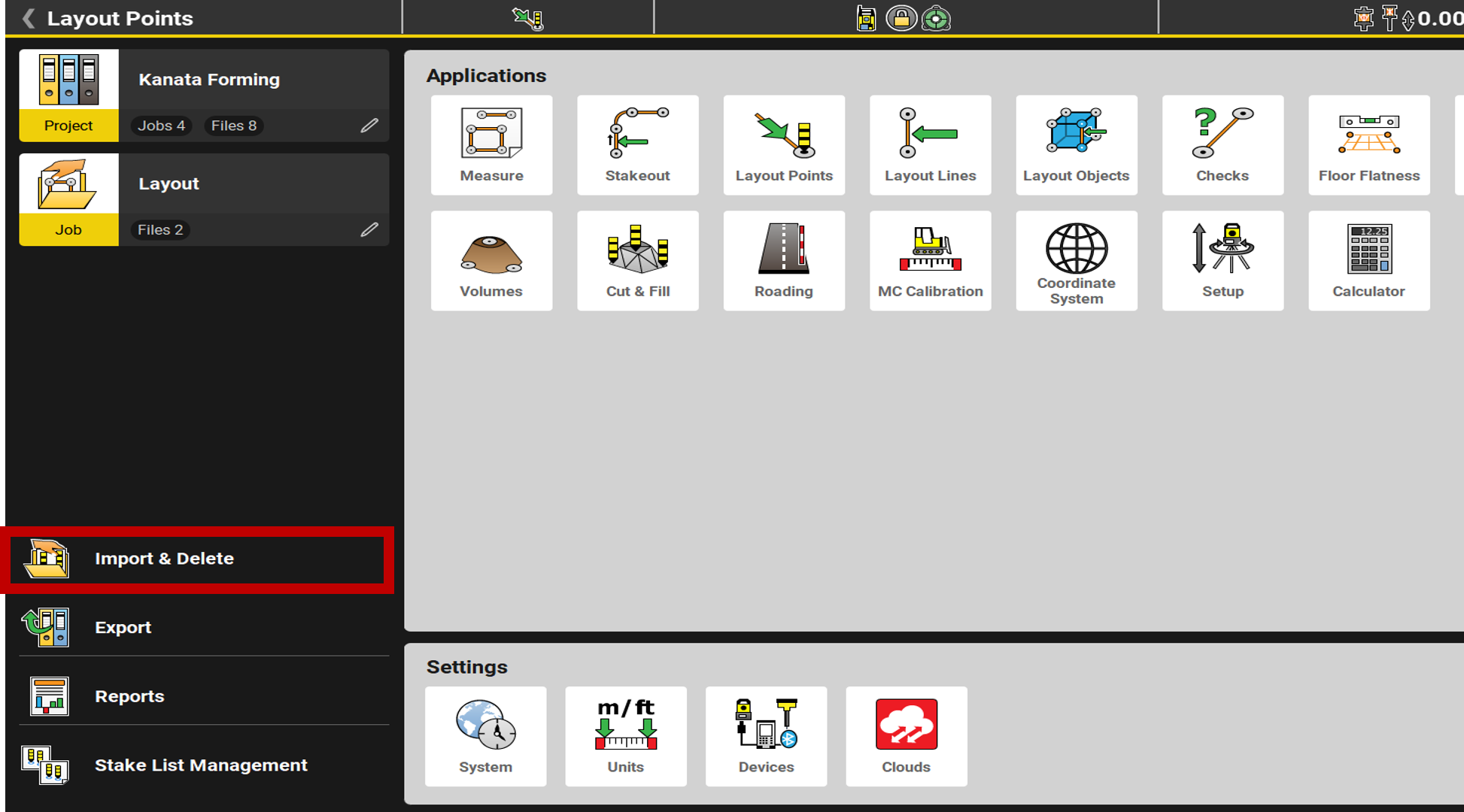
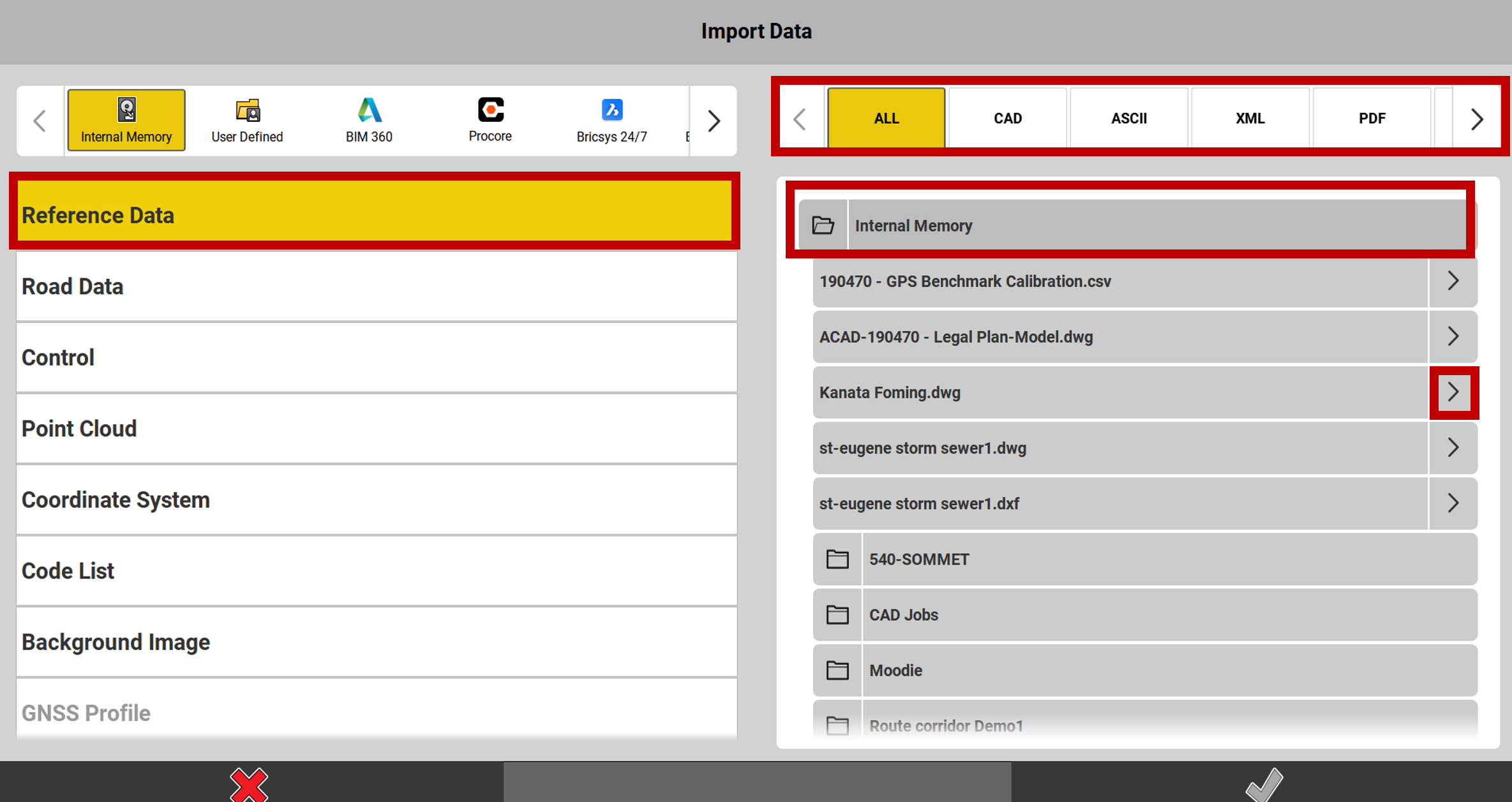
3.Select the source of the data to import (internal memory, USB, cloud...).
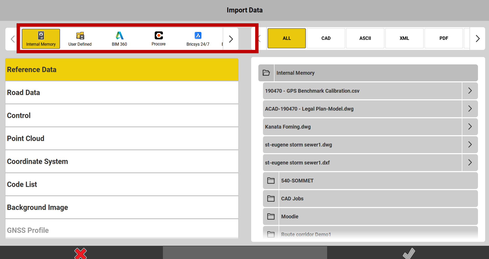
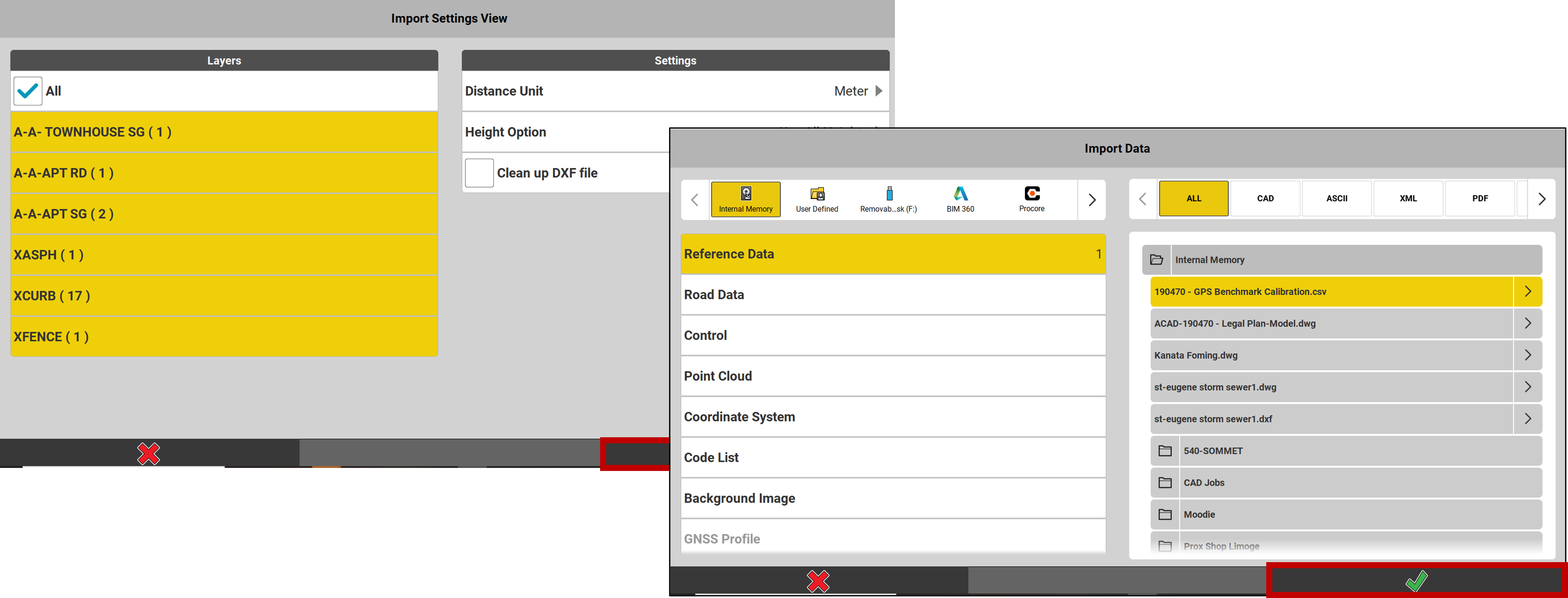
4.Select Reference data.
5.Possibility to choose the type of file you want. This will sort the files displayed.
6.Open the folder where the file to be imported is located.
7.Press the arrow to the right of the file name.
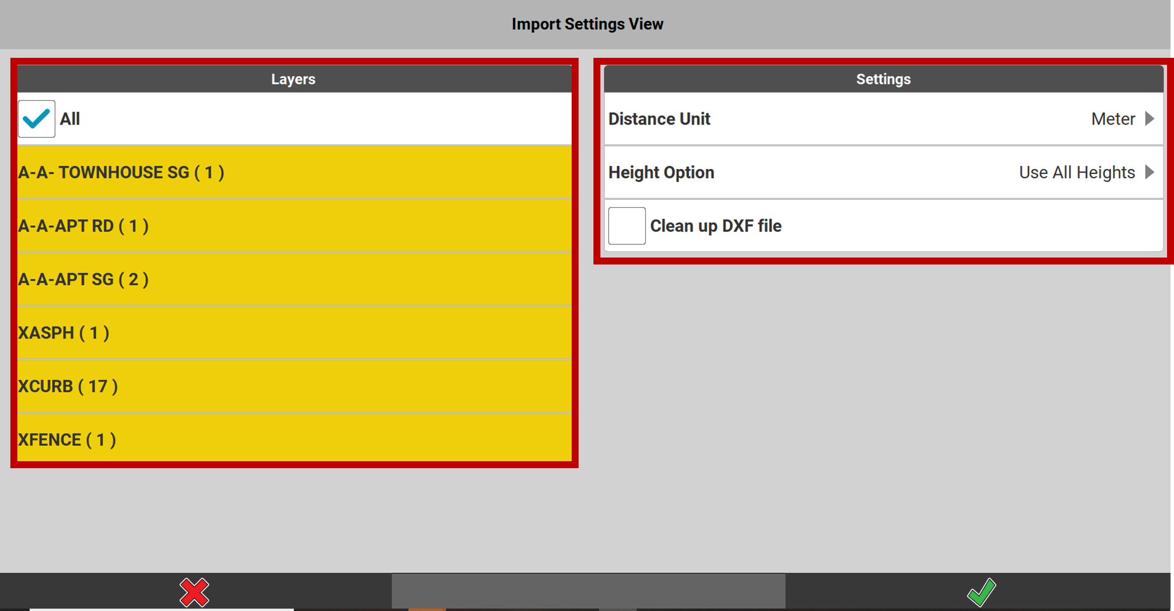
8.Select the Layers you wish to import. It is recommended that you import all of them, as you will then be able to turn the layers on and off as needed.
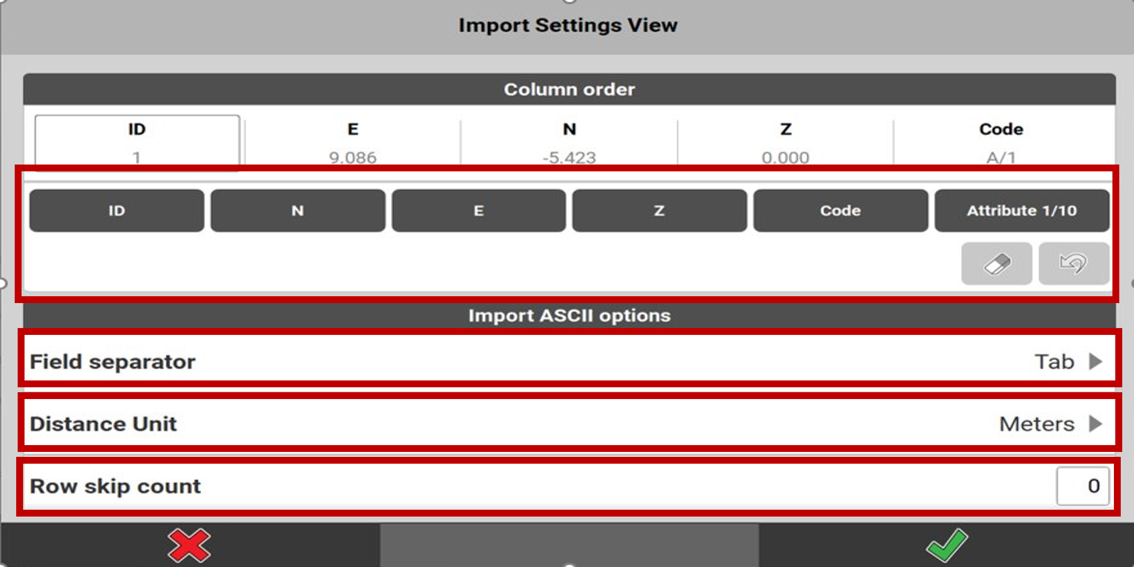
9.Set the Import Parameters. The distance unit is very important. You need to know in which unit the plan was drawn. For other parameters it is recommended to use the settings shown below.
10. Press the checkmark
11. It is then possible to import other files from the same source (USB, Internal Memory...). To do this, return to step #4. Otherwise, press the checkmark again
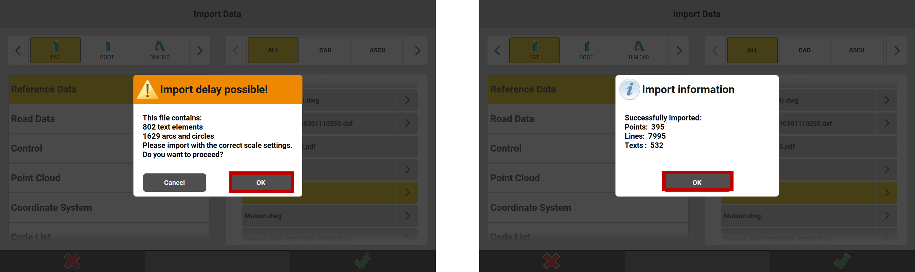
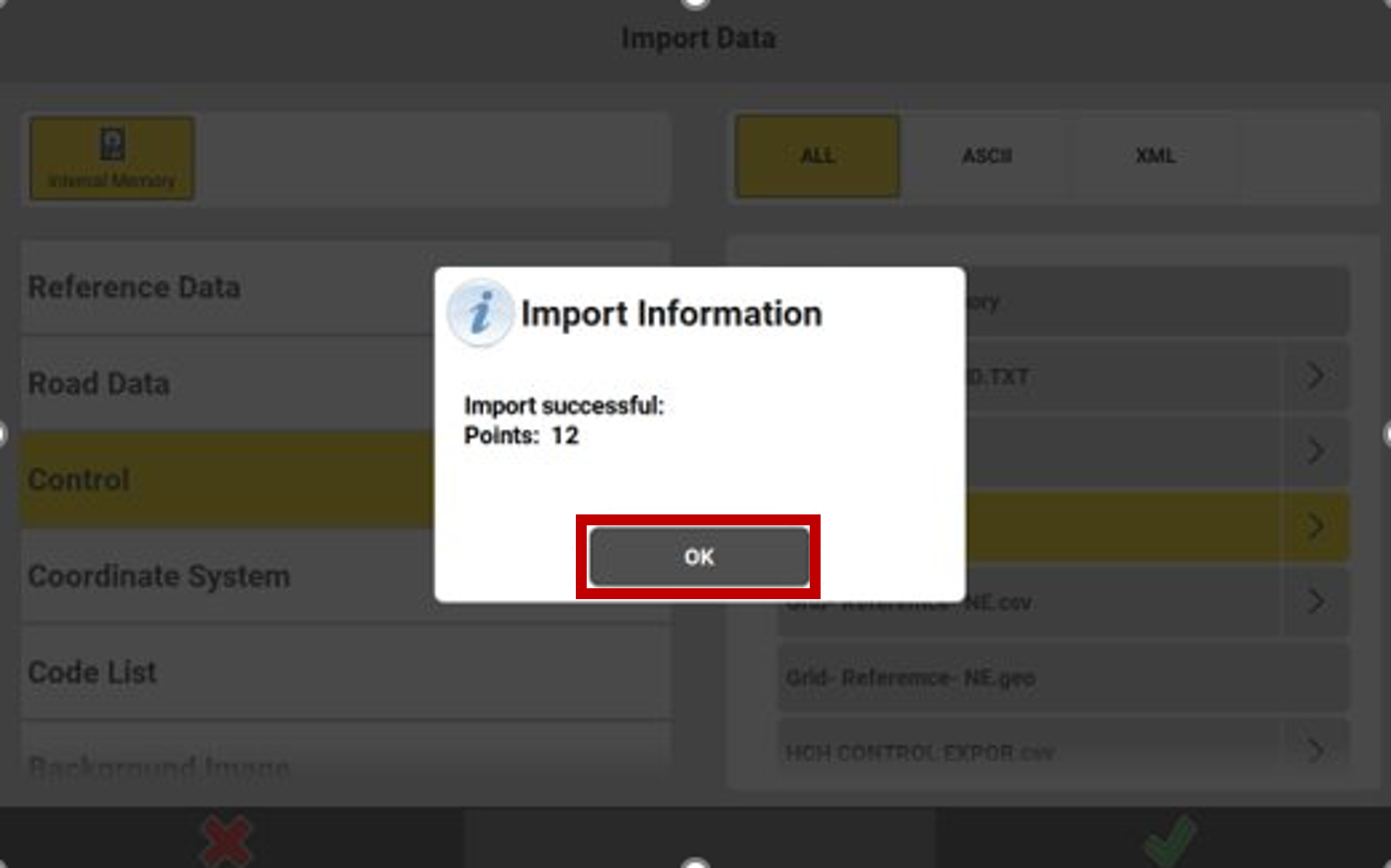
12. A warning message may appear, this is just information. Press OK
13. A message confirms the number of items imported. Press OK
Creation of a list of points
You can create lists of points from Excel or from a text file:
In Excel you must put your IDentifiers, Coordinates (E, N, H), in separate columns.
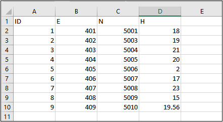
* Do not put comma ( , ) as decimal separator, you must put points.
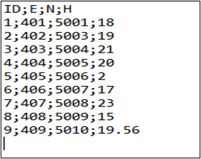
In a text file (.TXT), you can use different column separators. Here are 2 examples below
With tabs between the coordinates
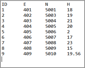
With semicolons; between the coordinates
Here are the steps to follow for importing a list of points:
Enter the Import and Delete menu and Press +
Take the time to determine the parameters correctly:
The field separator (tab, comma, ...)
The distance unit
The number of lines to ignore at the beginning of the file (in the example = 1 line).
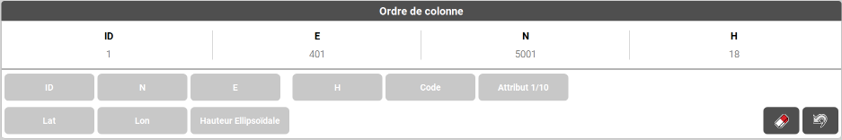
Once these parameters are set, we need to determine the order of the columns.
In the file to be imported below, we see the order ID ─ E ─ N ─ H.
Press these column values on the gray buttons in the same order.
Check the order of the coordinates and press the checkmark
* If a mistake is made at this stage, you will find your points outside your working area.
A message confirming successful import appears. Press OK
* If an error message appears, check your file to be imported in a text editor or an Excel spreadsheet.
PDF presentation files
The PDF format is a standard for paper plans, generally unsuitable for work in surveying software: it is a file type to be avoided!
For a PDF plan to be intelligently usable, it must:
•Be vector based (created from CAD software, not a photo)
•Contain a single page
•To be at a 1:1 scale
In almost all cases, the PDF files that contractors receive do not meet these requirements. The file must then be reworked using CAD software.
Furthermore, even if the file meets these requirements, some objects simply do not pass through iCON and several uneeded elements saturate the user's view.
Finally, PDFs do not support layers, which are a standard in construction projects. Layers facilitate intelligent data visualization.
The text elements take random shapes
No layers are available in the manager
The legend is present and cannot be removed.
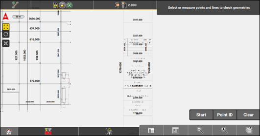
Some objects are not recognized by ICON.
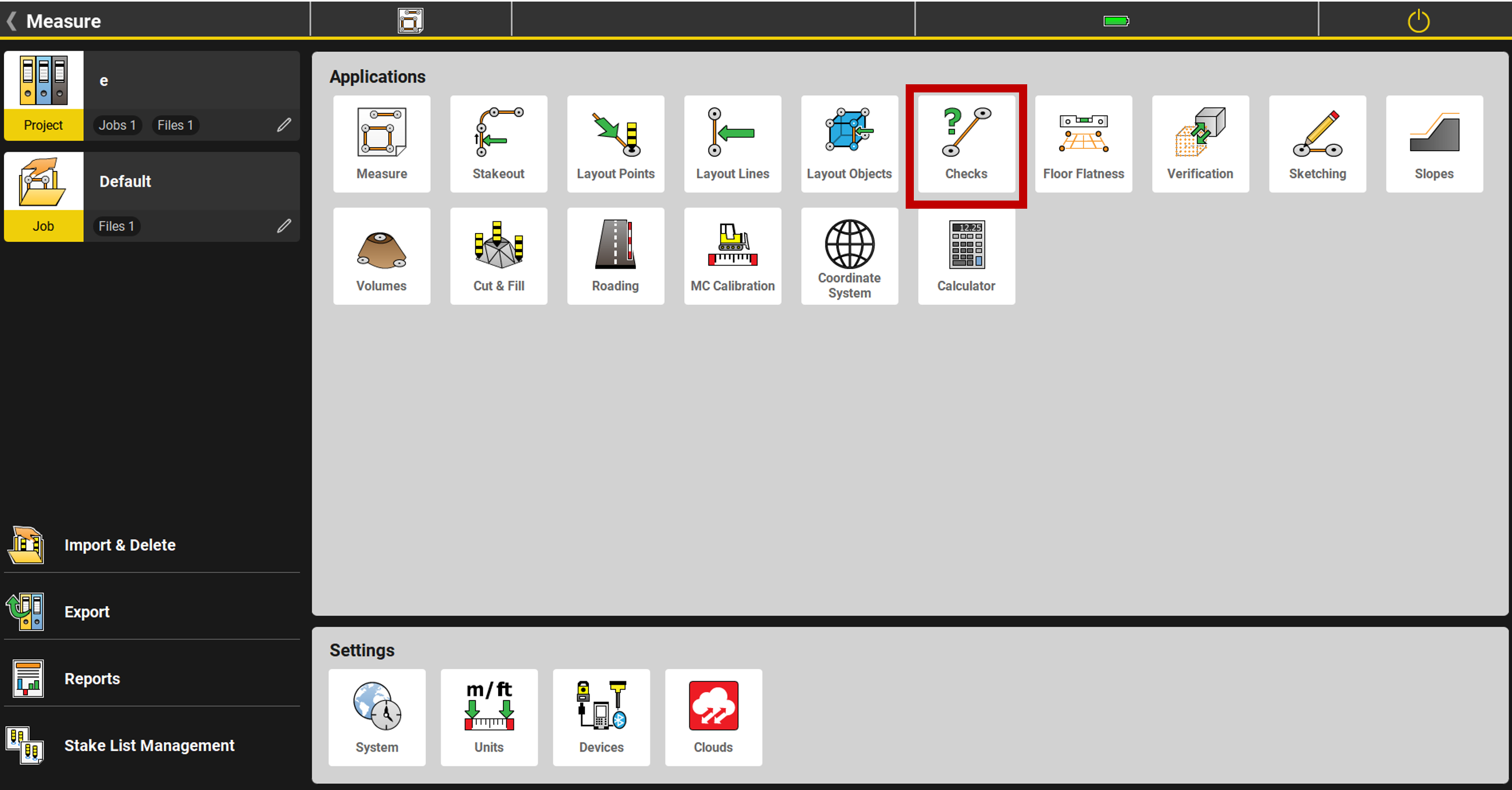
Checks
After importing a plan or a list of points, it is crucial to verify that it has been done correctly. The import parameters are crucial in the processing of the data by the iCON software.
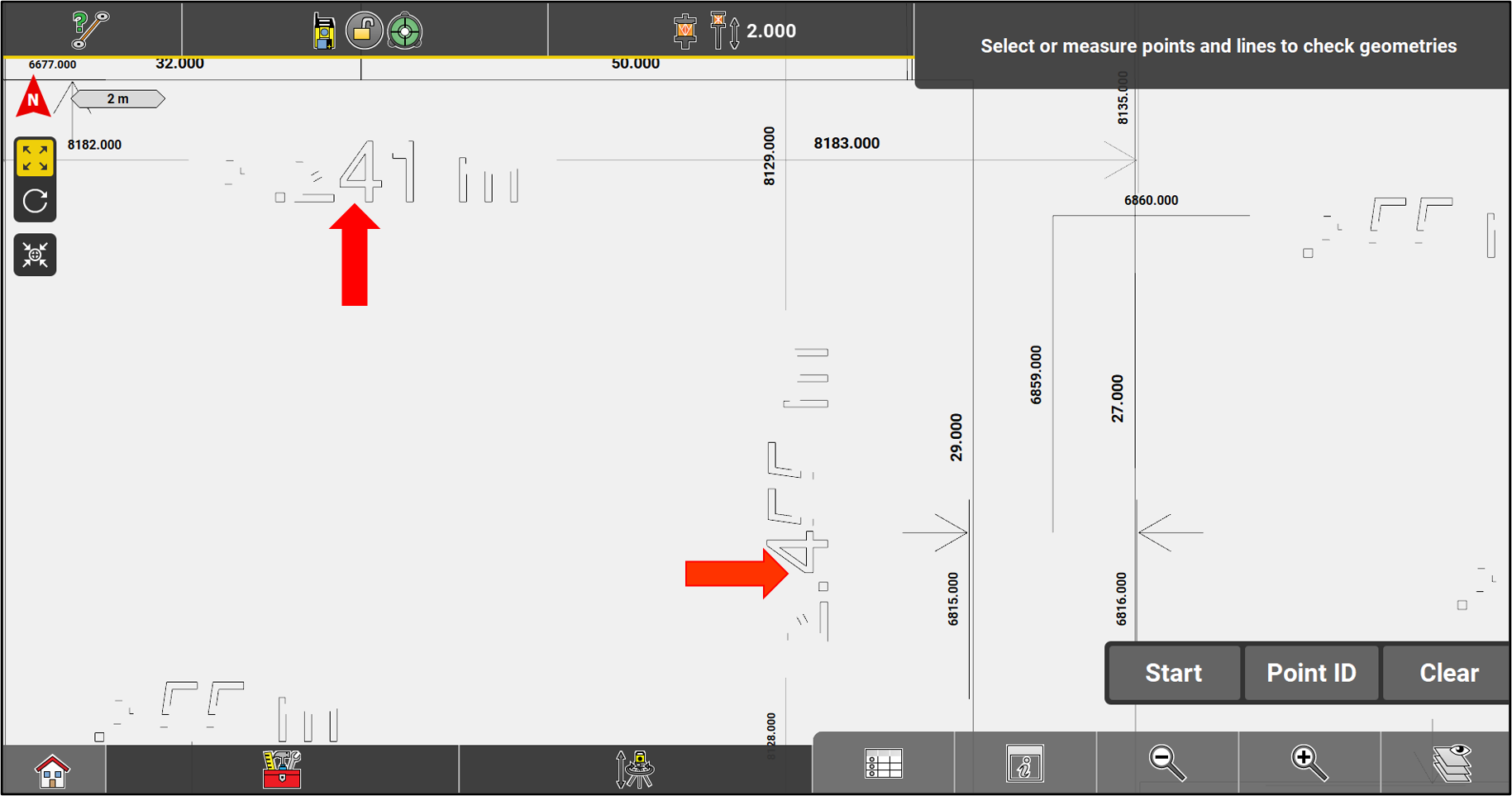
From the main menu, access the Checks application.
Select an element in the plan to check its size.
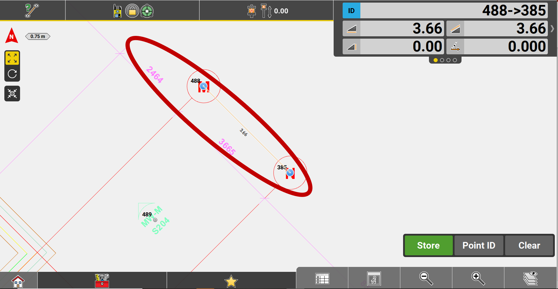
If a network of stations has been imported, make sure their positions make sense with the plan.
Check the scale at the top left of the screen. It should indicate a length that makes sense with the plan.
- If the distances in the plan are wrong, the error was probably made in the choice of distance units.
- If the station network is not located in the right place, check the Column Order during import.
* In both cases, you can go back to the Import Delete menu to delete your file and reimport it with the correct settings.
CAD file cleaning
In order to avoid problems and to lighten the CAD drawings, it is important to put only the elements that are essential for the field work. It is often necessary to make changes in the DWG or DXF. It is also possible to separate them into several.
Items to be deleted or converted:
- External references
- Blocks
- Spline
- Hatches
- Dimensions
- Multileaders
- Multiple texts
- Title blocks
* Generally, if the plan is georeferenced but its orientation has been reshaped for presentation, iCON automatically resets the plan to the correct coordinates. However, there may be times when the following procedure is required before exporting.
The following is a list of recommended cleanup work to be done on a drawing in CAD software before importing into iCON;
- Give the UCS command, then Enter.
- W for World, then Enter.

- Use the command PLAN, then Enter.
- C for Current UCS, then Enter.

External refrences
Use the XREF command, right-click on the external reference and choose Bind --> Insert so that it becomes a block belonging to the drawing instead of an external reference.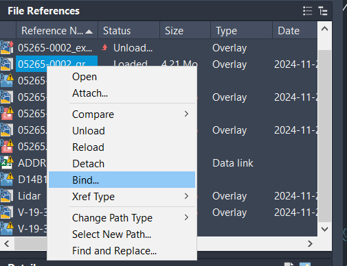

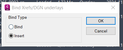
Repeat these steps for each external reference of interest
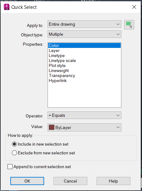
With the QSELECT command, you can quickly make selections according to object types and certain characteristics
QSELECT (Quick Select) command is accessible by typing QSE.
In the drop-down menu, select the desired objects.
- For a new selection
- Add to selection
- Delete from selection